Orrery Grad Cap
About
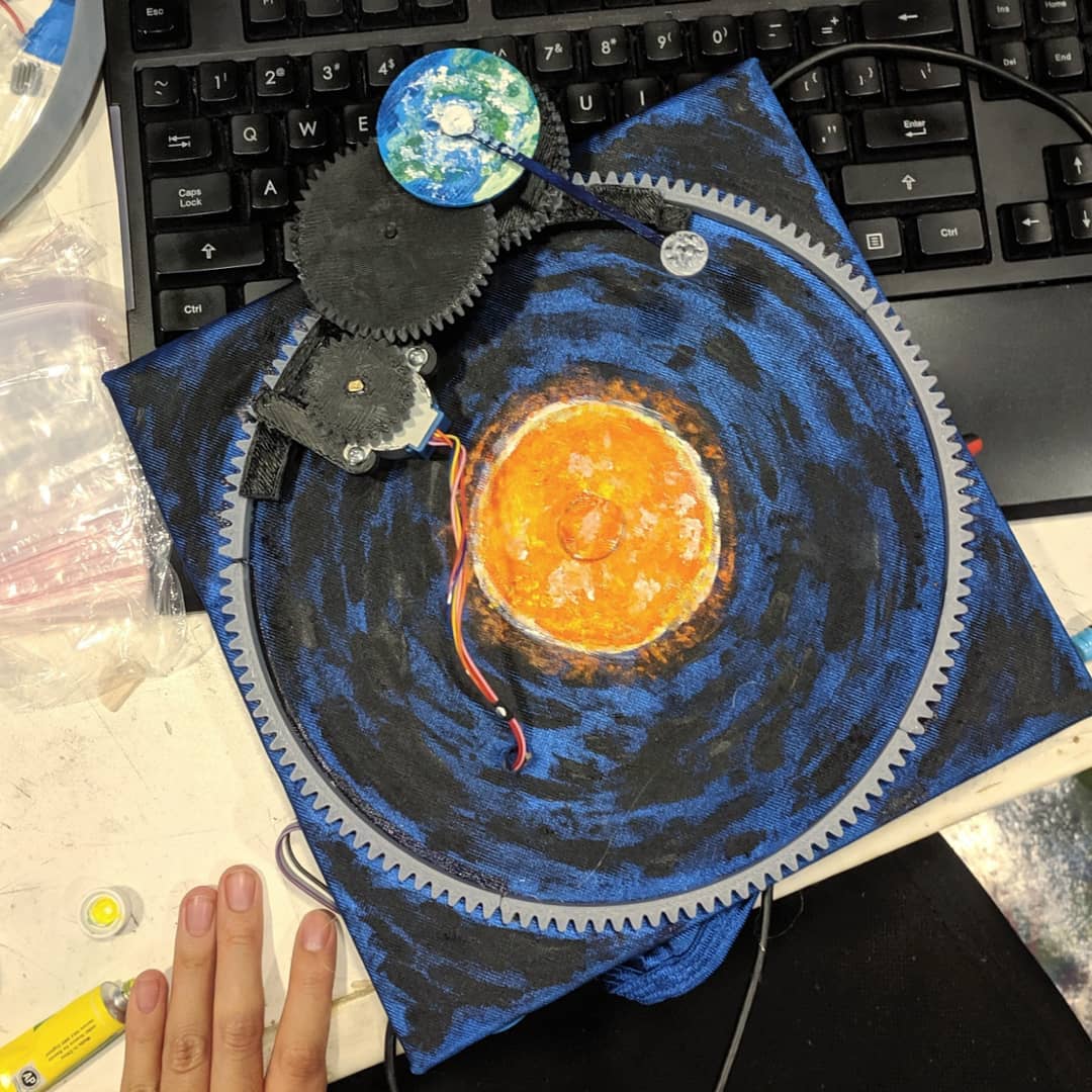
The most recent installment in my over-the-top space-themed mortarboard designs. This was my graduation cap for my associate’s degree from Tunxis Community College.
This basic orrery illustrates a simplified model of the rotation of the Earth about its axis, the Earth’s orbit around the Sun, and the Moon’s orbit around the Earth. It uses 3D printed gears and a stepper motor to drive the absolute speed of the system.
Unlike most of my projects, the circuit driving the stepper motor doesn’t have a microcontroller. Instead, it uses digital logic ICs to drive the motor at a continuous speed.
Design
Mechanical
This sketch shows the relationships between the rotation speeds of the components. The grad cap orrery used different gear ratios to achieve these different rotation speeds with only one driving motor.
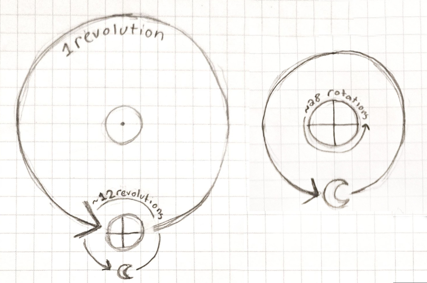
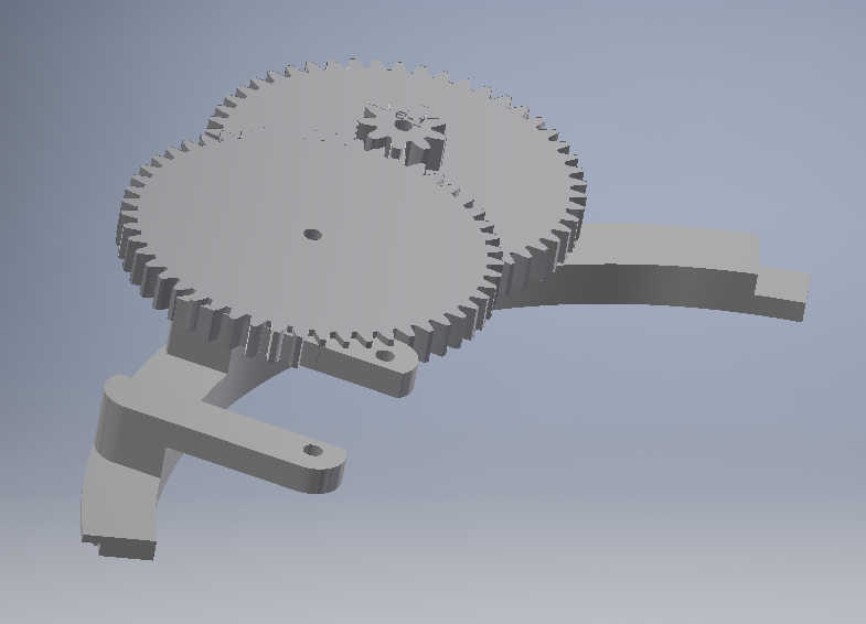
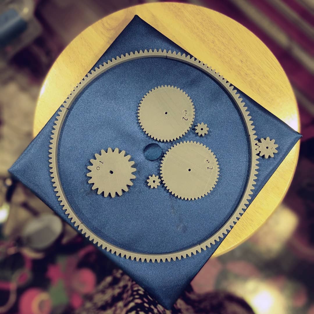
In order to get the directions of the Earth and Moon rotations to match, as well as keeping gear sizes reasonably small, I used two sets of gears with the same gear ratios, approximately 1:5.2 (more specifically, sqrt(27)). A2 and B1 are printed fused together, and share the same center point, so for every one rotation of A1, B1 and A2 both rotate ~5.2 times, and B2 rotates 27 times.
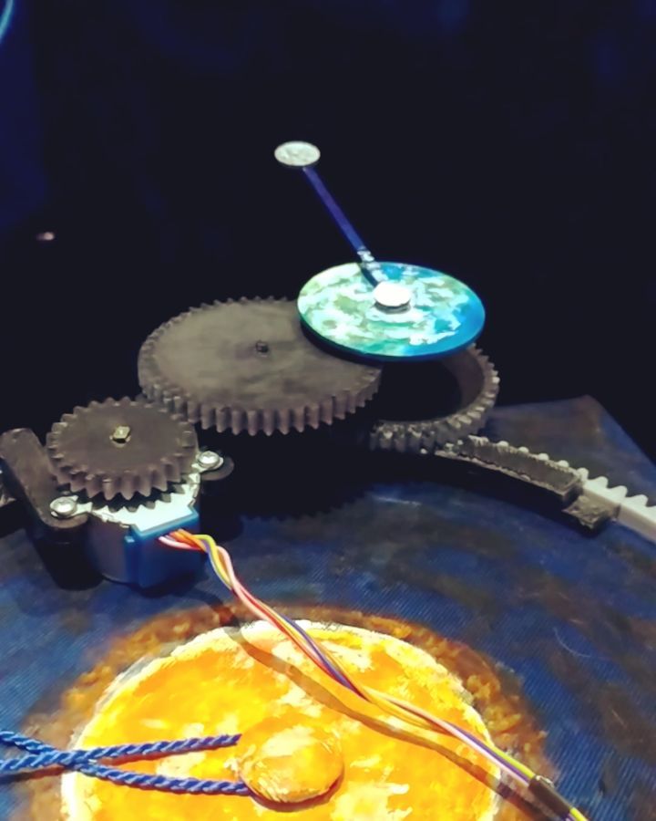
Another tricky thing was getting the moon and Earth to spin about the same point. This was achieved by having their gears spin on the same rod. Gear B2 can freely spin on the rod, but A1 is press fit and glued on. The actual moon piece is glued to the top of the rod, which spins at the same speed as the moon gear, and below it, the Earth can spin at its faster rate.
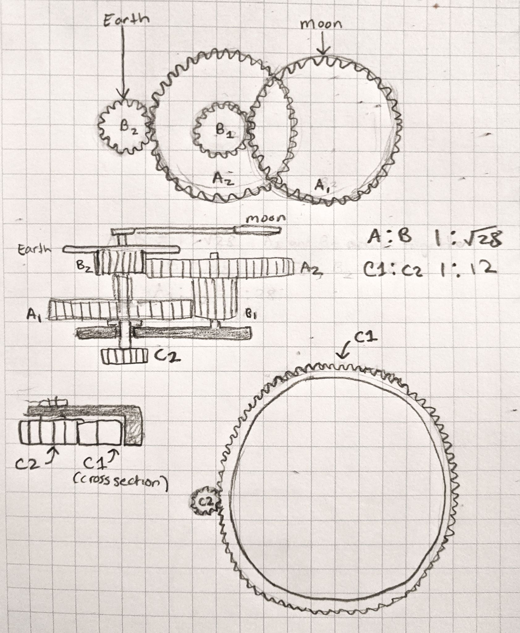
The Earth’s revolution around the Sun is also driven based off of the speed of the Moon’s revolution. Gear C2 is also fixed to the shaft, and rotates at the same speed as the other moon components. It has a gear ratio of approximately 12:1 compared to the big ring gear. The ring gear was also 3d printed and was glued to the surface of the hat. Gear C2 lets it “walk” the whole assembly around the hat/sun sort of like a rack and pinion.
This whole assembly isn’t really properly captured (it was, after all, built a few days before graduation!) so if you flip it over the Earth and Moon assembly just fall off the hat, but otherwise it stays on just fine even held at 90 degrees.
The stepper motor is mounted to the assembly and drives A2 with its own gear. The gear ratio of this affects how the torque is applied by the motor as well as the overall speed of the system. I remember originally doing calculations to try to get it around 1 hour per “year,” but turning it on now, it seems to be moving a bit faster than that.
Electrical
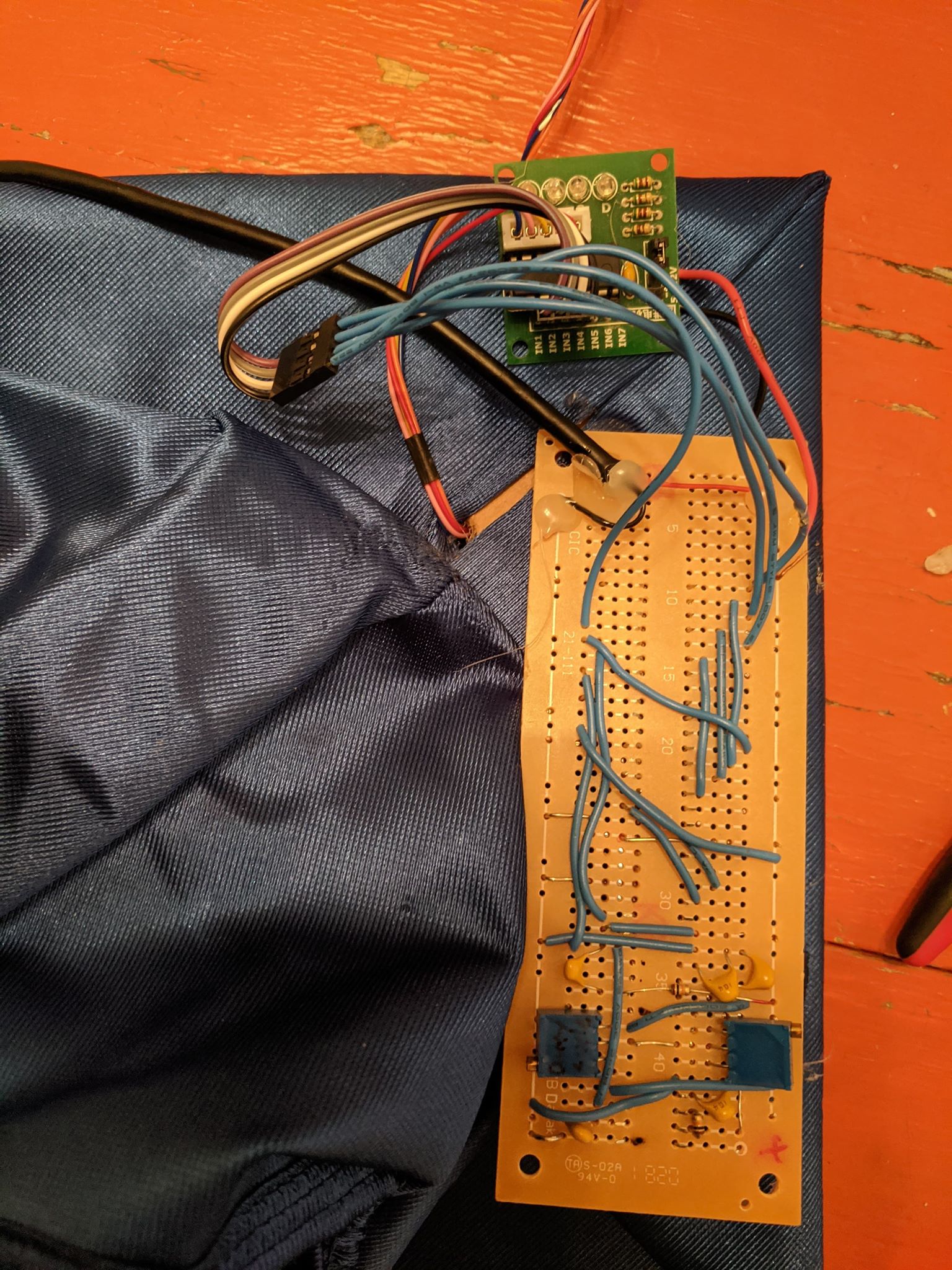
The circuit that drives this orrery is made of logic ICs - no microcontroller and no code necessary. It only needs to drive a stepper motor in one direction at a constant speed, a task pretty suitable for a timer, counter, and decoder.
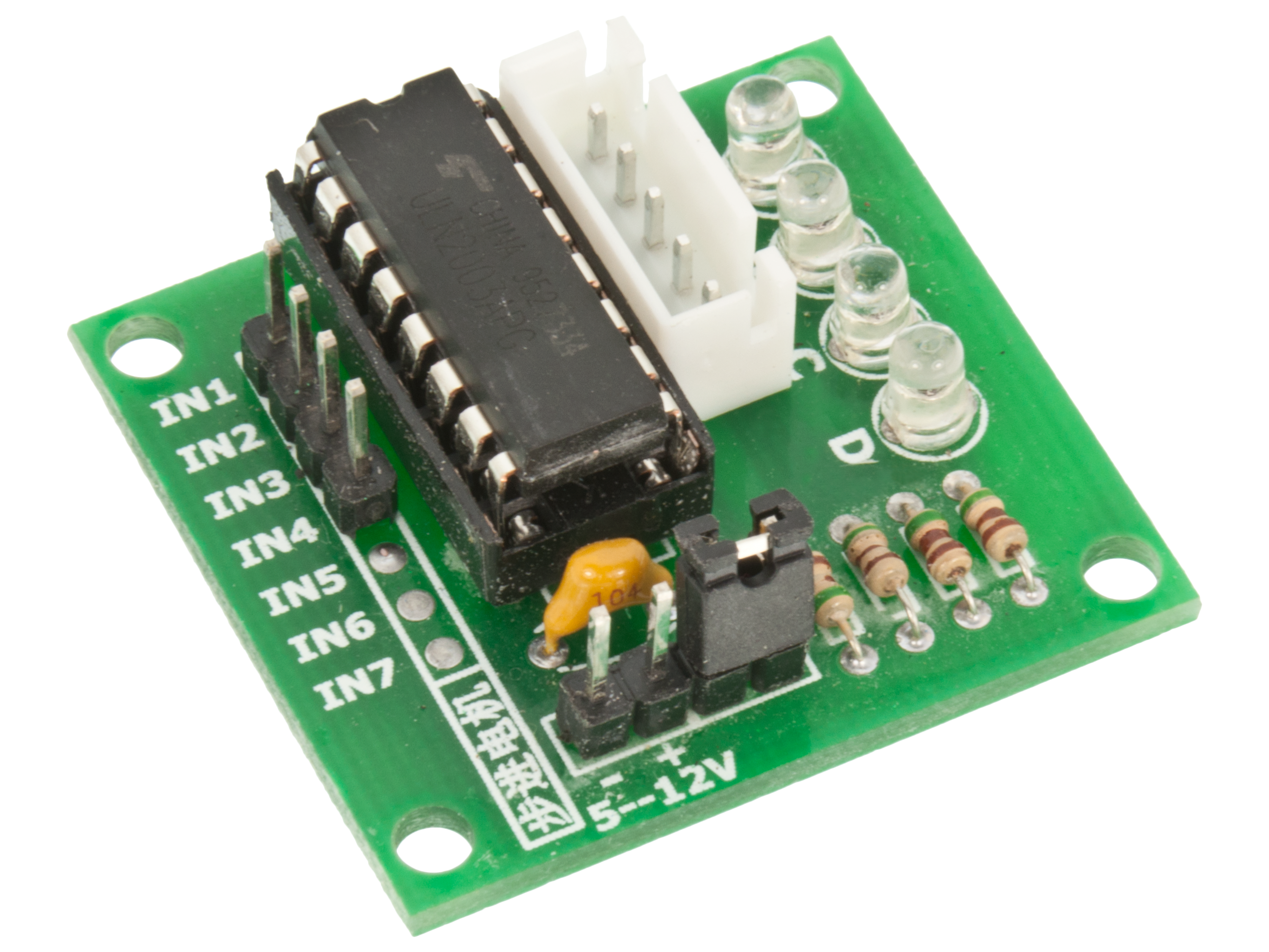
The stepper motor “driver” board I used was a little ULN2003A breakout - it has convenient connectors, some built in passives, and indicator LEDs that show you which coil is being energized (great for debugging!). So to spin the motor, you need to energize the coils in sequential order.
The whole system was powered off of a 5V USB power bank, using a cut off USB cable that’s long enough to hide the battery in a pocket.
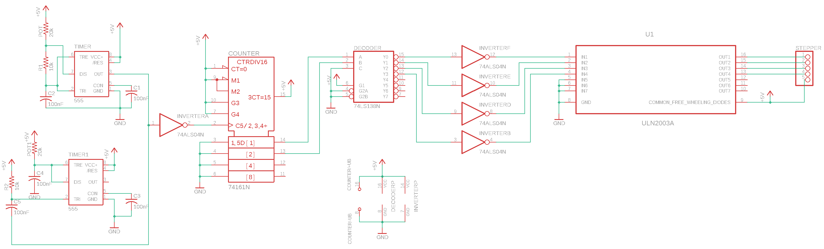
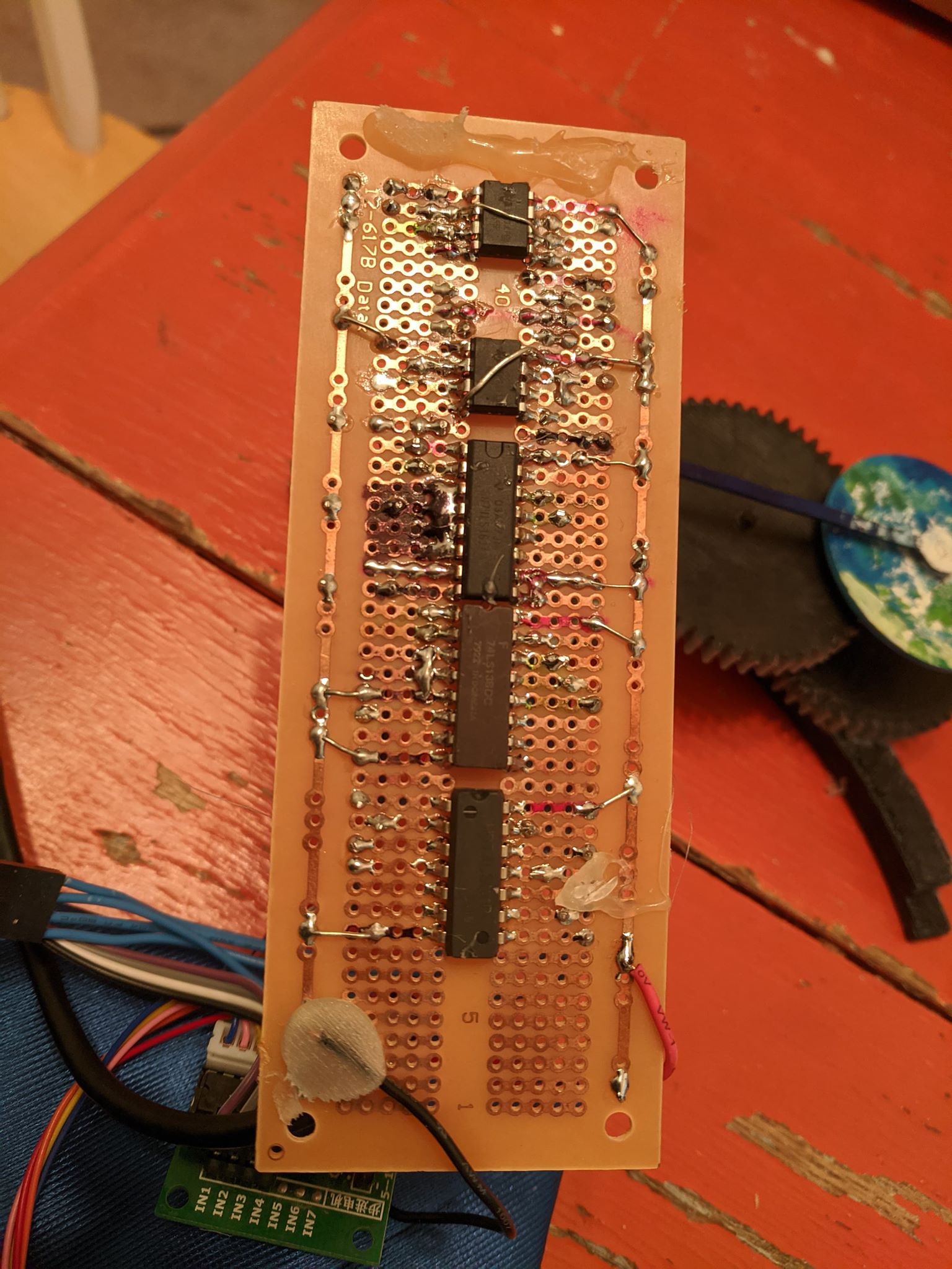
I drew this schematic based on the board 7 months after the fact, since I can’t find the original. There are 2 555 timers on the board, but the 2nd one is not hooked up. I believe it was originally to control the final pulse width of the output of the stepper motor, but that was scrapped.
The timer that is connected is configured as an astable multivibrator and serves as a clock, setting the speed for the whole system.
This clock signal is inverted, then goes to a 74161 synchronous 4-bit counter module. I only need the first two output bits of the binary counter, as there are only 4 coils. The counter is set to continuously count up, since it just cycles through the states {0, 1, 2, 3} regardless of overflow in the higher bits.
These states become the input to a 74138 decoder. This decoder has inverted outputs, so they are active LOW, so when the address sent to it is 0, it pulls output 0 to ground, while the rest are normally high; with address 1, output 1 is pulled LOW, and so on. It would have been simpler if I got a non-inverted decoder, but this was just a component I had lying around. I used a 7404 hex inverter chip (one of the inverters was already used with the clock signal!) to flip these outputs, and connected those signals to the ULN2003 inputs.
Speed Calculations
The potentiometer value on the schematic (which is just represented as a resistor) is not up to date. I measured it and it seems to be set at around 65k (it’s a 1M pot). The resistor is a 10k, and the cap is marked 104 which is 100 nF / .1 uF.
There are various astable multivibrator calculators available online. I used this one. Inputting these values gets me a frequency of 169.76 Hz, with an 88% duty cycle. In this case, duty cycle doesn’t matter too much, as the counter is trigged on a rising edge. The counter therefore updates at ~170 Hz (or, about every 6 milliseconds), and therefore the stepper motor makes a full step every 6 ms.
According to this source the stepper motor I used (28BY-48) has 2038 steps per revolution (full step mode). Therefore, the gear on the stepper motor takes 12.23 seconds to make a full rotation.
Unfortunately I don’t know the gear ratio between that gear and A1 or B2, but I had originally wanted the assembly to take 1 hour to orbit around the sun. 1 hour for one rotation of C1 –> 1/12 hour (5 minutes) per moon cycle. A1 rotates at this same rate, and A1: B1 is 1/5.2, so B1 (and therefore also A2) must rotate about once every minute. 57.69 sec / 12.23 sec = 4.72, so the gear ratio must have been about 1:4.72.
Estimating the actual gear ratio based on counting the teeth on the two gears, it appears to actually be closer to 2:1. So in its current configuration it’s actually going over twice as fast!
Media
Image Gallery
click to enlarge